Comprehending Multilayer PCBs and HDI PCBs
Multilayer PCB Fundamentals
Multilayer PCBs consist of multiple layers of copper-clad substrates laminated together. These boards typically have two or more conductive layers, separated by insulating materials. The layered structure allows for increased circuit density and improved signal routing capabilities. Multilayer PCBs are widely used in various electronic applications due to their versatility and cost-effectiveness.
Key features of multilayer PCBs include:
- Multiple conductive layers (usually 4, 6, 8, or more)
- Through-hole vias for inter-layer connections
- Increased circuit density compared to single or double-sided boards
- Improved EMI shielding capabilities
- Suitable for a wide range of applications
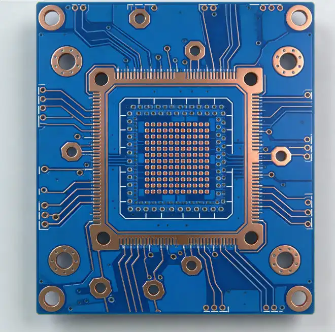
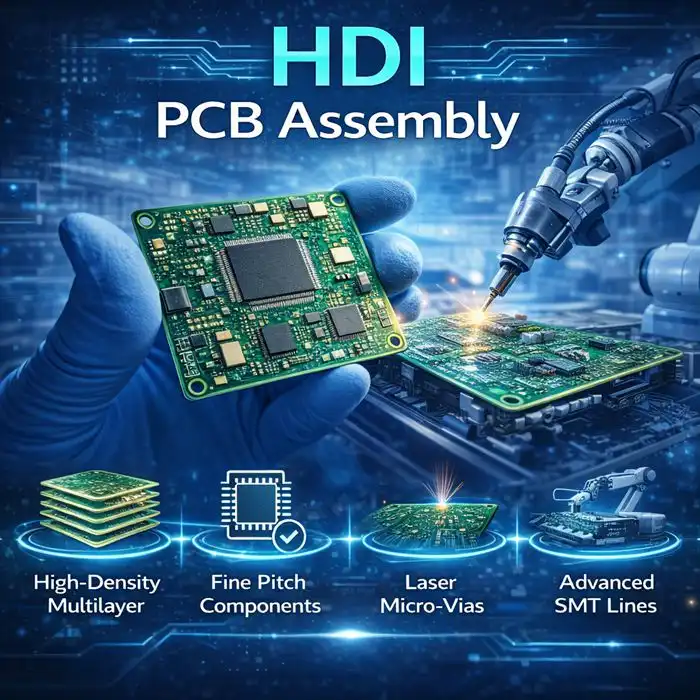
HDI PCB Technology Overview
HDI PCBs represent an advanced PCB technology that pushes the boundaries of circuit density and performance. These boards utilize microvias, finer traces, and more compact layer stacking to achieve higher component density and improved signal integrity. HDI PCBs are particularly beneficial for high-frequency applications and devices requiring miniaturization.
Distinctive characteristics of HDI PCBs include:
- Microvias with diameters smaller than 150 microns
- Higher circuit density compared to traditional multilayer PCBs
- Finer trace widths and spacing (typically less than 100 microns)
- Improved signal integrity due to shorter signal paths
- Enhanced thermal management capabilities
Signal Integrity Comparison: Multilayer vs HDI PCBs
Signal Path Length and Impedance Control
Signal path length plays a crucial role in maintaining signal integrity. HDI PCBs have a significant advantage in this aspect due to their compact design and use of microvias. The shorter signal paths in HDI PCBs result in reduced signal propagation delays and less signal degradation. This is particularly important for high-speed digital circuits where timing is critical.
Moreover, HDI PCBs offer superior impedance control due to their finer trace widths and tighter layer-to-layer spacing. This allows for more precise impedance matching, which is essential for maintaining signal quality in high-frequency applications. Multilayer PCBs, while capable of good impedance control, may require more complex design considerations to achieve similar results.
Electromagnetic Interference (EMI) and Crosstalk Reduction
Both multilayer and HDI PCBs can be designed to mitigate EMI and crosstalk issues. However, HDI PCBs have some inherent advantages in this area. The compact layer stacking and use of microvias in HDI PCBs allow for better isolation between signal layers, reducing the potential for crosstalk. Additionally, the shorter signal paths in HDI PCBs naturally result in less electromagnetic radiation, further reducing EMI concerns.
Multilayer PCBs can achieve good EMI and crosstalk performance through careful layer stack-up design and the use of ground planes. However, they may require more layers or additional shielding techniques to match the EMI performance of HDI PCBs in some high-frequency applications.
High-Frequency Performance
When it comes to high-frequency performance, HDI PCBs generally outperform traditional multilayer PCBs. The reduced parasitic capacitance and inductance in HDI designs, coupled with shorter signal paths, result in improved signal integrity at high frequencies. This makes HDI PCBs particularly suitable for applications such as 5G communications, high-speed computing, and advanced radar systems.
While multilayer PCBs can be designed for high-frequency applications, they may require more complex design techniques and additional layers to achieve comparable performance to HDI PCBs. This can lead to increased board thickness and potentially higher costs for high-frequency multilayer designs.
Choosing Between Multilayer and HDI PCBs
Application Requirements
The choice between multilayer and HDI PCBs ultimately depends on the specific requirements of your application. Consider the following factors:
- Signal frequency: HDI PCBs are generally preferred for high-frequency applications (above 1 GHz)
- Circuit density: If extreme miniaturization is required, HDI PCBs offer superior component density
- Signal integrity requirements: For applications demanding the highest level of signal integrity, HDI PCBs are often the better choice
- Cost considerations: Multilayer PCBs are typically more cost-effective for less demanding applications
- Production volume: HDI PCBs may be more economical for high-volume production due to their smaller form factor
Design Complexity and Manufacturability
HDI PCBs offer greater design flexibility and can accommodate more complex circuit layouts in a smaller area. However, this increased complexity can also lead to more challenging manufacturing processes. HDI PCB fabrication requires specialized equipment and expertise, which may impact production costs and lead times.
Multilayer PCBs, while potentially limited in terms of circuit density, are generally easier to manufacture and have a wider range of available fabrication facilities. This can translate to lower production costs and faster turnaround times for less demanding applications.
Cost-Benefit Analysis
When deciding between multilayer and HDI PCBs, it's essential to perform a thorough cost-benefit analysis. While HDI PCBs may have higher initial fabrication costs, they can offer long-term benefits such as:
- Reduced overall board size, potentially lowering material costs
- Improved product performance, potentially increasing market competitiveness
- Enhanced reliability due to better signal integrity and thermal management
- Potential for reduced assembly costs due to higher component density
Conversely, multilayer PCBs may be more cost-effective for applications that don't require the advanced features of HDI technology. They offer a good balance of performance and cost for many mainstream electronic products.
Conclusion
In the debate of multilayer PCB vs HDI PCB for signal integrity, HDI PCBs generally come out on top, especially for high-frequency and high-density applications. Their advanced design features, including microvias and finer traces, allow for superior signal performance and reduced electromagnetic interference. However, multilayer PCBs remain a viable and cost-effective solution for many applications where extreme miniaturization or the highest levels of signal integrity are not critical.
When selecting a PCB technology for your project, carefully consider your specific requirements, including signal frequency, circuit density, and budget constraints. For those seeking top-tier signal integrity and miniaturization capabilities, partnering with an experienced HDI PCB manufacturer can provide significant advantages. These suppliers can offer expert guidance on design optimization and ensure high-quality production of your HDI PCBs, maximizing the benefits of this advanced technology for your electronic products.
FAQ
What is the main difference between multilayer and HDI PCBs?
The main difference lies in their construction and density. HDI PCBs use microvias and finer traces to achieve higher circuit density and better signal integrity compared to traditional multilayer PCBs.
Are HDI PCBs always better than multilayer PCBs?
Not necessarily. While HDI PCBs offer superior performance in many aspects, multilayer PCBs are still suitable and more cost-effective for many applications that don't require extreme miniaturization or high-frequency performance.
What applications benefit most from HDI PCB technology?
HDI PCBs are particularly beneficial for high-frequency applications, mobile devices, aerospace and defense electronics, and any product requiring miniaturization and high signal integrity.
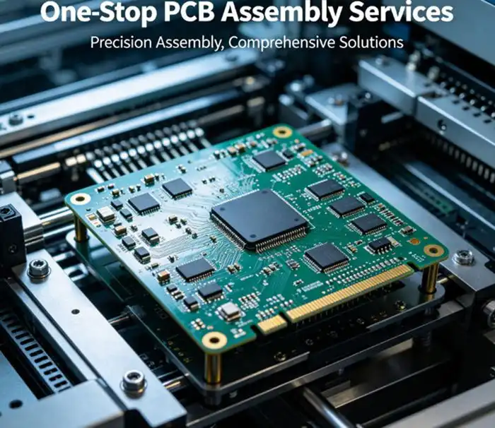
Comprehensive PCB Solutions for Optimal Signal Integrity | Ring PCB
At Ring PCB, we specialize in delivering high-quality PCB solutions tailored to your specific signal integrity requirements. Our expert team can guide you through the selection process between multilayer and HDI PCBs, ensuring you choose the optimal technology for your application. With our state-of-the-art manufacturing facilities and rigorous quality control processes, we guarantee exceptional performance and reliability in every PCB we produce. Contact our experienced PCB manufacturing team today at [email protected] to discuss your project needs and experience the Ring PCB difference in PCB fabrication and assembly.
References
1. Johnson, H. W., & Graham, M. (2003). High-speed digital design: a handbook of black magic. Prentice Hall PTR.
2. Coombs, C. F. (2008). Printed circuits handbook. McGraw-Hill Education.
3. Ritchey, L. W., & Zasio, J. J. (2005). Right the first time: a practical handbook on high-speed PCB and system design. Speeding Edge.
4. Hall, S. H., & Heck, H. L. (2009). Advanced signal integrity for high-speed digital designs. John Wiley & Sons.
5. Bogatin, E. (2010). Signal and power integrity-simplified. Prentice Hall.