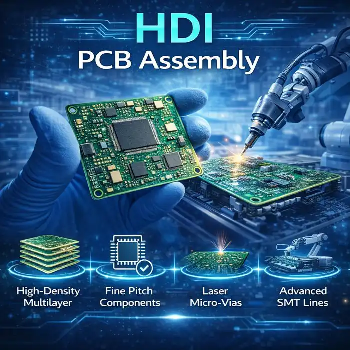
HDI PCB Assembly vs Standard PCB Assembly
HDI PCB assembly vs. standard PCB assembly are two options for making printed circuit boards. The difference between them has a big effect on product performance, manufacturing prices, and time-to-market strategies. Ultra-High Density Interconnect (HDI) technology is a cutting-edge method that uses microvias, fine-pitch components, and layered designs to provide better electrical performance in small packages. Standard PCB assembly is a more standard method, but it has been shown to work reliably in situations where density requirements are not as strict. This comparison helps purchasing managers make smart choices based on technical requirements, costs, and the skills of the suppliers.

Comprehending HDI PCB Assembly and Standard PCB Assembly
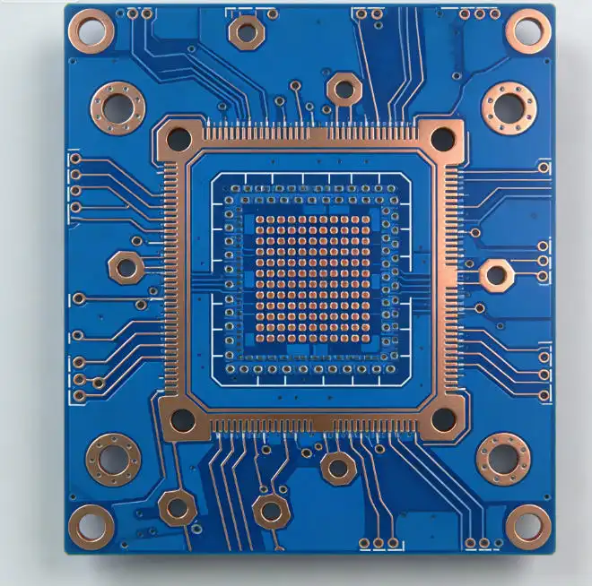
The main difference between these ways of putting things together is the number of connections and how hard they are to make. HDI PCB Assembly uses advanced manufacturing methods like sequential lamination, ultra-fine trace shapes, and laser-drilled microvias to fit a huge number of components onto a very small amount of board space.
Key Characteristics of HDI Technology
Microvias on HDI boards usually have diameters between 50 and 150 microns. This lets layers next to each other link directly without taking up important routing room. With matched spacing, these boards can handle trace lengths as thin as 25 microns, which lets signals travel quickly while reducing electromagnetic interference. With the sequential build-up process, makers can make structures with more than 20 layers that are very complicated and still work very well electrically.
Standard PCB Assembly Features
Standard PCB assembly uses standard through-hole via technology, which has widths that are usually bigger than 200 microns. Trace lengths on these boards are usually between 100 and 200 microns, and they use standard subtractive etching methods. Even though they are easier to make, standard PCBs work well in situations where size restrictions and data density needs are modest.
The way the parts are made directly affects the design's freedom and the places where the parts can be placed. HDI technology lets designers send signals under ball grid array (BGA) packages and other parts with a lot of pins, which makes the best use of board space. For bigger via structures and routing channels, standard building methods need more careful placement of parts.
Technical Comparison: HDI PCB Assembly vs Standard PCB Assembly
When you look at the technical specs, you can see that these two ways of putting things together have very different speed levels. The better features of HDI PCB Assembly make electrical performance, temperature management, and mechanical stability better in a way that can be measured.
Signal Integrity Performance
Because the interconnects on HDI boards are shorter and there are fewer parasitic effects, the signal quality is better. The smaller via sections reduce signal bounce and crosstalk, which makes it possible to reliably operate at frequencies above 10 GHz. The accuracy of impedance control is usually within ±5%, compared to ±10% for standard boards. This is very important for keeping signal quality good in digital systems that work quickly.
Thermal Management Capabilities
The multiple layers and higher copper density in HDI boards make them better at getting rid of heat. Integrated thermal vias and improved copper distribution help control the heat that comes from high-power parts, making the device more reliable and consistent in its performance. Standard boards handle heat well enough for normal power levels, but for difficult uses, you may need to find other ways to remove heat.
Manufacturing Complexity and Quality Control
To make HDI, you need high-tech tools like laser cutting systems, plasma desmear units, and advanced testing technologies. To keep layer-to-layer orientation within ±25 microns during the sequential lamination process, precise registration control is needed. Automated optical inspection (AOI), electrical testing at each build-up layer, and thorough final inspection processes are all part of quality control routines that make sure products are delivered without any problems.
Standard PCB production uses tried-and-true methods like standard printing, mechanical cutting, and single-step laminate. Quality control checks for things like accurate measurements, electricity connection, and certain surface finish requirements. The tried-and-true method of making usually leads to better production output with less technical complexity.
Choosing the Right PCB Assembly Method for Your Project
Based on performance goals, cost constraints, and time limits, the project needs determine the best way to put things together. When procurement teams know what the unique needs of an application are, they can choose the best technology while keeping price constraints in mind.
Applications Favoring HDI Technology
HDI PCB Assembly works great for tasks that need to be small, have a lot of parts, and have great electrical performance. HDI technology is used in consumer goods like smartphones, tablets, and wearable tech to make small designs that don't lose any usefulness. Because they are smaller and more reliable, these features are good for medical surgical implants. HDI chips are used in aerospace and defense systems to reduce weight and improve signal security in important situations.
Standard PCB Assembly Applications
Standard building methods are still the best choice for situations where cost-effectiveness and stability are more important than shrinking the size of the part. Standard PCBs are often used in industrial control systems, power supplies, and automotive uses because they are well-made and have established supply lines. The cost savings and easier production methods that come with standard assembly are great for high-volume consumer goods that don't have to be a certain size.
Evaluation Criteria for Supplier Selection
To find the right manufacturing partner, you need to carefully look at their professional skills, quality certifications, and services they offer. Suppliers should show that they have experience with the technology being considered by giving customer examples and proof of their abilities. Quality certifications like ISO 9001, IATF 16949, and UL recognition show that a company is committed to making sure that their products meet regular quality standards. Support for design for manufacturability (DFM) helps improve ideas so that they can be made more cheaply and with higher rates.
Overview of HDI PCB Assembly Materials and Manufacturing Steps
The materials and methods used in HDI PCB Assembly have a direct effect on how well and how reliably the product works. The better features of HDI technology are made possible by using advanced substrate materials and specialized production methods. To keep quality standards, the process must be carefully controlled.
Specialized Materials for HDI Construction
High-performance dielectric materials with low loss slope and great heat stability are used in HDI boards. Changes to epoxy resins and polyimide films give them the electrical traits needed for high-frequency operation while keeping their shape even when the temperature changes. Copper foils that are very thin allow for fine-line etching while still having enough current carrying ability for power delivery networks.
Manufacturing Process Overview
The building process starts with a standard layered core and then moves on to layers that are changing between dielectric and wire. Laser drilling makes microvias with exact control over dimensions and few areas touched by heat. Before the next layer is added, each one is processed separately, which includes filling, surface preparation, and electrical testing. This method makes sure that the layers stick together well and that the structure is electrically connected all the way through.
Quality Control Protocols
At every step of the manufacturing process, strict quality control measures keep an eye on important factors. Cross-sectional analysis checks the quality of the formation and the bonding of the layers, while impedance testing checks the electrical performance against the design specifications. Automated visual screening systems find differences in size and flaws on the surface of things that could affect how well an assembly works. Final electrical testing makes sure everything works before it is sent to be put together.
Challenges and Solutions in HDI PCB Assembly
Making HDI PCB Assembly products is a difficult technical process that needs special tools, trained workers, and methods that work best. Knowing about these problems and how to solve them helps buying teams figure out what suppliers can do and set reasonable deadlines for projects.
Technical Manufacturing Challenges
For reliable electrical links between layers, microvia formation precision is still very important. Laser drilling factors need to be carefully managed to get uniform hole sizes while causing as little damage as possible to the materials around the hole. As feature areas get smaller, it's more important than ever that the registration between layers is accurate. This calls for more advanced alignment systems and process tracking tools.
It's harder to place components accurately when there are more of them and the pads are smaller. Pick-and-place machines need to be able to place things accurately to within ±25 microns while still meeting speed standards. To get uniform deposit amounts on small aperture sizes, solder paste printing needs fine-pitch cutouts and paste rheology that is just right.
Process Optimization Strategies
A full design for manufacturability (DFM) analysis must be done during the planning step for HDI manufacturing to go smoothly. When design teams and factory partners work together early on, they can find problems before they commit to production. As part of process optimization, thermal profile development for complicated circuits, selective soldering techniques for mixed-technology boards, and advanced inspection methods for quality assurance are all things that are done.
Statistical process control monitoring collects and analyzes data to allow for ongoing growth. Real-time feedback tools let workers know when parameters aren't being met before quality problems happen. Predictive repair programs make sure that equipment works the same way during all production runs and reduce downtime that comes up out of the blue.
With these optimization techniques, experienced makers can keep lead times low and get defect rates below 200 parts per million. By spending money on new machines and improving processes, they are able to make output stable enough to meet the strict needs of HDI applications.
Conclusion
Choosing between HDI and normal PCB assembly has a big effect on how well a product works, how much it costs to make, and how competitive it is in the market. HDI PCB Assembly delivers superior electrical performance, enhanced miniaturization capabilities, and improved reliability for demanding applications, while standard assembly offers proven cost-effectiveness for conventional requirements. Procurement managers need to carefully look at project requirements, supplier skills, and long-term strategy goals. To make sure the best results, successful execution needs to work with experienced manufacturers who have the right certifications, state-of-the-art tools, and thorough quality control systems.

FAQ
What are the main advantages of HDI PCB Assembly over standard PCB technology?
HDI PCB Assembly provides significantly higher component density, improved electrical performance, and enhanced signal integrity compared to standard boards. The microvia technology enables direct connections between layers without consuming routing space, while finer trace geometries support high-frequency applications with reduced electromagnetic interference. These advantages translate into smaller product sizes, better performance, and increased functionality within compact form factors.
How does HDI technology impact manufacturing costs and lead times?
HDI manufacturing typically requires 20-40% higher costs compared to standard PCB assembly due to advanced materials, specialized equipment, and complex processing requirements. Lead times generally extend 2-3 weeks beyond standard board schedules to accommodate sequential lamination and additional quality control steps. However, the performance benefits and size reduction capabilities often justify the additional investment for applications requiring miniaturization and enhanced electrical characteristics.
Can HDI PCB Assembly support low-volume production requirements?
Modern HDI manufacturers accommodate low-volume production through flexible manufacturing approaches and optimized setup procedures. Batch processing techniques enable cost-effective prototype and pilot production runs while maintaining quality standards. Many suppliers offer expedited services for rapid prototyping and small-batch requirements, supporting accelerated product development cycles and market introduction timelines.
Partner with Ring PCB for Superior HDI PCB Assembly Solutions
Ring PCB Technology delivers exceptional HDI PCB Assembly services backed by 18 years of manufacturing expertise and comprehensive quality certifications including ISO 9001, IATF 16949, and UL recognition. Our advanced manufacturing facility features state-of-the-art laser drilling equipment, sequential lamination capabilities, and supports up to 48-layer multilayer circuit boards with industry-leading precision. We provide competitively priced solutions with 24/7 online support and continuous 7-day production schedules, ensuring faster delivery times than standard industry practices. Contact our engineering team at [email protected] to discuss your HDI PCB Assembly requirements and experience our comprehensive turnkey manufacturing capabilities.
References
1. Institute for Printed Circuits. "High Density Interconnect Technology Guidelines and Design Rules." IPC Standards Documentation, 2023.
2. Electronics Manufacturing Association. "Advanced PCB Assembly Techniques: HDI Technology Implementation." Manufacturing Best Practices Journal, Vol. 45, 2023.
3. International Electronics Research Institute. "Comparative Analysis of HDI versus Standard PCB Performance Metrics." Technical Research Publication Series, 2023.
4. Society of Electronic Engineers. "Microvia Technology and Sequential Lamination Processes in Modern PCB Manufacturing." Engineering Applications Quarterly, Issue 3, 2023.
5. Global Electronics Manufacturing Council. "Cost-Benefit Analysis of HDI Technology Adoption in Consumer Electronics." Industry Market Analysis Report, 2023.
6. Advanced Materials Research Foundation. "Substrate Materials and Dielectric Properties in High-Density Interconnect Applications." Materials Science Journal, Vol. 78, 2023.

Welcome to Ring PCB! Share your inquiry, and receive a tailored quotation!

Ring PCB, your trusted partner for PCB & PCBA Full Turnkey Solutions