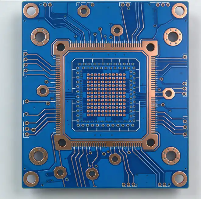
How to Minimize Signal Loss in 12-Layer HDI PCBs for High-Speed Applications
Impedance control, design, and material selection must all be carefully considered for minimizing signal loss in 12-layer HDI PCBs for high-speed applications. In order to minimize insertion loss and crosstalk, professional HDI PCB Assembly services make use of sophisticated laser drilling techniques, low-loss dielectric materials, and exact layer stack-up arrangements. Maintaining signal integrity in intricate multilayer structures working at high frequencies requires careful microvia placement, regulated impedance routing, and optimum ground plane design.

Comprehending Signal Loss in 12-Layer HDI PCBs
One of the most important issues that engineers dealing with high-speed 12-layer HDI circuits must deal with is signal loss. Electrical signals experience many types of deterioration when they pass through intricate multilayer structures, which can jeopardize the performance of devices and the quality of data transmission.
Types of Signal Loss in Complex Multilayer Designs
In 12-layer HDI systems, insertion loss, return loss, and crosstalk interference are the main types of signal degradation. As a signal passes via transmission lines and vias, its amplitude diminishes, a phenomenon known as insertion loss. When signal reflections back toward the source are caused by impedance mismatches, return loss occurs. When target signals are interfered with by electromagnetic fields from nearby traces, crosstalk occurs, producing undesired noise and distortion.
Because of the close proximity of several signal layers and the intricacy of via arrangements, these loss mechanisms become especially noticeable in high-density connection systems. Due to conductor losses, dielectric absorption, and electromagnetic interaction between layers, the 12-layer arrangement offers many chances for signal deterioration.
Root Causes of Signal Degradation
A key factor in the creation of signal loss is material properties. Signal intensity is directly attenuated by dielectric materials with large dissipation factors, which transform electrical energy into heat. High-speed performance, notably in HDI PCB Assembly, can be significantly impacted by frequency-dependent losses introduced by subpar substrate materials.
Signal integrity results are greatly impacted by layer stacking configurations. Impedance discontinuities caused by improper spacing between the signal and reference planes result in reflections and signal distortion. Structures that join several layers can function as parasitic components, adding capacitance and inductance that deteriorate signal quality.
Signal loss can also caused by changes in the manufacturing process. Dimensional tolerances, uneven copper plating, and inconsistent drilling can all result in impedance changes that affect the way signals are transmitted. These elements highlight how crucial it is to choose seasoned assembly partners who are aware of the subtleties of high-speed multilayer fabrication.
Analyzing Core Challenges in 12-Layer HDI PCB Signal Integrity
A thorough grasp of connection technologies and how they affect electrical performance is necessary to maintain optimal signal integrity in 12-layer HDI assemblies. Effectively addressing the distinct issues posed by the intricate interplay between design features and production processes calls for specialist knowledge.
Microvia Impact on Signal Path Integrity
In HDI designs, microvias are essential linkages between layers, but how they are implemented has a big impact on the properties of signal transmission. In contrast to through-hole connections, blind and buried vias have distinct impedance profiles, necessitating meticulous modeling and optimization to reduce reflections.
Microvias' electrical performance is influenced by their aspect ratio; larger aspect ratios generally result in more parasitic effects. Compared to mechanical drilling, laser-drilled microvias provide better dimensional control, allowing for more consistent electrical properties and enhanced signal integrity.
Coupling and crosstalk generation are impacted by placement in relation to signal traces. While preserving the essential communication between layers, strategic microvia placement can lessen electromagnetic interference.
Controlled Impedance and Layer Stack-up Considerations
It is necessary to precisely control copper weight, dielectric thickness, and trace shape in order to provide constant impedance control throughout 12 layers. Maintaining goal impedance levels while meeting routing density requirements requires careful design of each signal layer.
When signals move between layers in multilayer architectures, reference plane continuity becomes crucial. Signal distortion and electromagnetic interference can be produced by return path discontinuities caused by splits or gaps in the ground and power planes.
Signal integrity results are directly impacted by the choice of high-performance substrate materials with low loss tangent values and stable dielectric constants. For demanding high-speed applications, advanced materials such as specialty glass weaves and low-loss polyimides offer excellent electrical performance.
Manufacturing Process Variables and Assembly Quality
Impedance control and signal integrity are affected by solder mask qualities, especially for surface-mounted components and fine-pitch devices. Predictable electrical performance throughout the assembly is ensured by uniform solder mask thickness and dielectric characteristics.
Signal transmission across multilayer interconnects is impacted by filling quality. Air gaps that can result in impedance discontinuities and reliability problems are eliminated by properly filled microvias. Advanced filling methods that use copper plating or conductive pastes offer the best mechanical and electrical performance.
Optimization Principles and Techniques to Minimize Signal Loss
Strategic design optimization and the application of advanced fabrication processes are necessary to achieve enhanced signal integrity in 12-layer HDI assemblies. Significant gains in high-speed performance are made possible by the combination of state-of-the-art technologies and tried-and-true engineering principles.
Advanced Fabrication Technologies for Enhanced Performance
Compared to mechanical drilling techniques, laser drilling technology offers remarkable precision for microvia production, allowing for smaller via sizes and tighter tolerances. Improved impedance control and less parasitic effects, which can deteriorate signal quality, are directly correlated with this increased precision.
Narrower traces and tighter spacing can be implemented with fine line technologies, boosting routing density while preserving regulated impedance characteristics. Particularly in HDI PCB Assembly, these features allow for lower overall board thickness and more effective layer use without sacrificing electrical performance.
Through the placement of passive components inside the PCB structure as opposed to the surface layers, component embedding techniques lower parasitic capacitance and inductance. This method removes package parasitics, which usually deteriorate high-frequency performance, and reduces signal path lengths.
Material Selection for Optimal Signal Transmission
High-performance HDI designs are based on low-loss dielectric substrates. When compared to conventional FR4 substrates, materials having dissipation coefficients less than 0.005 greatly minimize signal attenuation. For demanding applications, advanced polyimide and liquid crystal polymer materials offer remarkable electrical characteristics.
The performance of the entire assembly is directly impacted by the use of high-quality components. Consistent electrical behavior across production quantities is guaranteed by components with tightly controlled parasitic characteristics and tolerance standards. Signal path discontinuities are minimized by surface-mount devices with well-designed packages.
The results of signal integrity are also influenced by conductive materials. Conductor losses are decreased by high-purity copper foils with smooth surface finishes, especially at higher frequencies where the skin effect becomes noticeable.
Design for Manufacturability Integration
Potential problems with signal integrity can be identified and fixed prior to production by early cooperation between the design and manufacturing teams. Theoretical performance goals can be met through realistic production procedures thanks to design for manufacturability principles.
Before physical prototyping, signal integrity simulation techniques verify design choices and forecast performance results. In order to reduce signal loss, advanced electromagnetic modeling capabilities allow for the optimization of via placement, layer stack-up, and routing algorithms.
Case Studies: High-Speed 12-Layer HDI PCB Applications with Minimized Signal Loss
Examples of real-world implementations show how optimization techniques can be used to provide better signal integrity performance. These case studies demonstrate how theoretical ideas result in quantifiable advancements in real-world applications.
Telecommunications Infrastructure Applications
For next-generation switching systems running at multi-gigabit data rates, a major producer of telecom equipment needed 12-layer HDI assemblies. For the application to preserve signal quality across intricate routing networks, very low insertion loss and little crosstalk were required.
Sequential build-up technology with laser-drilled microvias and low-loss polyimide substrates was the solution. Critical signal layers were positioned between designated reference planes through careful layer stack-up optimization, which offered superior impedance control and electromagnetic shielding, especially in HDI PCB Assembly.
Crosstalk reduction surpassed 20dB at working frequencies, and insertion loss improvements of 15% over traditional designs were confirmed by signal integrity testing. The customer was able to maintain production cost goals while meeting their aggressive signal quality standards thanks to these performance improvements.
Automotive High-Speed Control Systems
For sophisticated driver assistance systems that required real-time data processing capabilities, a producer of automotive electronics needed dependable 12-layer HDI solutions. Temperature cycling, vibration resistance, and electromagnetic compatibility requirements were among the particular difficulties the application posed.
These issues were resolved by specialist material selection and optimal filling procedures in custom assembly processes. Low-loss properties preserved signal integrity throughout automobile working temperature ranges, while high-temperature polyimide substrates offered thermal resilience.
The effective deployment of improved signal quality in production vehicles was made possible by thorough testing. The improved electrical performance decreased warranty claims for communication failures and increased system reliability.
Best Practices and Key Takeaways
A thorough focus on material selection, design optimization, and manufacturing process control is necessary for the successful application of signal loss minimization techniques. When these components are combined, synergistic improvements are produced that outweigh the advantages of separate optimizations.
Critical Success Factors for Signal Integrity
High-performance HDI assemblies are built on the foundation of material selection. Achievable performance levels are directly impacted by optimal component selection, high-quality copper conductors, and low-loss dielectric materials. Investing in high-quality materials usually yields substantial benefits due to increased dependability and electrical performance.
Optimization of stack-up designs necessitates a careful balancing act between manufacturing capabilities, mechanical limits, and electrical needs. Achieving challenging signal integrity goals is made possible by planned layer allocation, controlled impedance design, and appropriate reference plane management.
Design intents are translated into production realities thanks to precise assembling procedures. Advanced manufacturing techniques that ensure consistent quality results and validate electrical performance include laser drilling, controlled impedance fabrication, and thorough testing.
Future Trends and Emerging Technologies
Signal integrity management skills will continue to increase thanks to emerging assembling technologies. New levels of high-speed performance will be made possible by revolutionary technologies, improved manufacturing precision, and advanced materials with even lower loss characteristics.
As the complexity of technology keeps expanding, collaborations with seasoned HDI specialists become more and more beneficial. Particularly in HDI PCB Assembly, manufacturers with demonstrated proficiency in advanced materials, precise fabrication, and thorough testing offer crucial support for successful product development and production scaling.
FAQ
What causes signal loss in 12-layer HDI PCB designs?
Signal loss in 12-layer HDI PCBs stems from multiple factors including dielectric material characteristics, via structure impedance mismatches, and electromagnetic coupling between layers. High dissipation factor materials convert signal energy into heat, while improper layer stack-up creates reflection points that degrade signal quality. Manufacturing variations in via drilling and copper plating can introduce additional impedance discontinuities.
How do microvias affect signal integrity in multilayer HDI assemblies?
Microvias create controlled impedance transitions between layers but can introduce parasitic inductance and capacitance that affect high-frequency performance. Laser-drilled microvias offer superior dimensional control compared to mechanical drilling, providing more predictable electrical characteristics. Proper microvia design and placement optimization minimize these parasitic effects while maintaining necessary layer connectivity.
What materials provide the best signal integrity performance for 12-layer HDI applications?
Low-loss polyimide and liquid crystal polymer substrates deliver superior electrical performance with dissipation factors below 0.005. These materials maintain stable dielectric properties across temperature and frequency ranges while providing excellent dimensional stability. High-purity copper foils with smooth surface finishes further reduce conductor losses at high frequencies.
How does layer stack-up design impact signal loss in HDI PCBs?
Layer stack-up directly influences impedance control, electromagnetic coupling, and signal transmission characteristics. Proper spacing between signal and reference planes ensures controlled impedance while minimizing crosstalk between adjacent traces. Strategic layer allocation and reference plane continuity management prevent signal degradation and electromagnetic interference issues.
Ring PCB Technology: Your Trusted HDI PCB Assembly Partner
Ring PCB Technology Co., Limited stands as your dedicated HDI PCB Assembly manufacturer, delivering innovative solutions for high-speed multilayer applications since 2008. Our comprehensive expertise encompasses custom 12-layer HDI designs, precision assembly processes, and advanced signal integrity optimization techniques that ensure superior performance in demanding applications.

Our vertically integrated manufacturing capabilities enable complete control over signal loss minimization strategies. We utilize state-of-the-art laser drilling equipment for precise microvia formation and advanced substrate materials with dissipation factors below 0.003 for exceptional electrical performance. Ring PCB's engineering team specializes in DFM optimization that reduces design risks while maintaining aggressive signal integrity targets.
With ISO9001, IATF16949, and UL certifications, our quality management systems guarantee consistent production outcomes. Our 24/7 manufacturing operations and three-shift engineering support provide rapid response times that significantly outperform standard delivery schedules. Manufacturing capabilities extend to 48-layer multilayer designs with ±7% impedance control, positioning Ring PCB as your ideal HDI PCB Assembly supplier for complex high-speed projects. Contact Ring PCB today at [email protected] to discuss your specific signal integrity requirements and discover how our advanced manufacturing capabilities can optimize your next high-speed design project.
References
1. Johnson, Howard, and Martin Graham. "High-Speed Signal Propagation: Advanced Black Magic." Prentice Hall Professional Technical Reference, 2003.
2. Bogatin, Eric. "Signal and Power Integrity - Simplified." Prentice Hall, 2nd Edition, 2009.
3. Hall, Stephen H., Garrett W. Hall, and James A. McCall. "High-Speed Digital System Design: A Handbook of Interconnect Theory and Design Practices." Wiley-IEEE Press, 2000.
4. Edwards, Terry, and Michael B. Steer. "Foundations of Interconnect and Microstrip Design." John Wiley & Sons, 4th Edition, 2016.
5. Thierauf, Scott C. "High-Speed Circuit Board Signal Integrity." Artech House Publishers, 2004.
6. Montrose, Mark I., and John L. Drewniak. "EMC and the https://www.turnkeypcb-assembly.com/sale-54340328-quick-turn-multilayer-pcb-manufacturing-for-high-power-supply-with-smt-assembly.html: Design, Theory, and Layout Made Simple." IEEE Press, 1999.

Welcome to Ring PCB! Share your inquiry, and receive a tailored quotation!

Ring PCB, your trusted partner for PCB & PCBA Full Turnkey Solutions