How to Troubleshoot and Repair Your PCB?
Troubleshooting and repairing a Printed Circuit Board (PCB) requires a systematic approach and attention to detail. Begin by visually inspecting the board for obvious issues like burnt components or loose connections. Use a multimeter to check for continuity and proper voltage levels. If you identify faulty components, carefully desolder and replace them. For more complex issues, employ specialized tools like oscilloscopes or logic analyzers. Remember that some PCB assembly problems may be due to design flaws or manufacturing defects, so consult the original schematics and specifications when necessary. Always prioritize safety by disconnecting power sources before working on the PCB.

Essential Tools and Techniques for PCB Troubleshooting
Effective PCB troubleshooting relies on having the right tools and knowing how to use them. A well-equipped workstation is crucial for diagnosing and repairing issues in PCB assemblies. Here are some essential tools and techniques to consider:
Multimeter: Your First Line of Defense
A quality digital multimeter is indispensable for PCB troubleshooting. It allows you to measure voltage, current, and resistance, helping you identify open circuits, short circuits, and faulty components. When using a multimeter on a PCB assembly, always ensure the board is powered off to prevent accidental shorts or damage to sensitive components.
Oscilloscope: Visualizing Signal Integrity
An oscilloscope is a powerful tool for analyzing signal waveforms in PCB assemblies. It can help you detect issues like signal distortion, noise, or timing problems that may not be apparent with a multimeter alone. When troubleshooting high-speed circuits or digital interfaces, an oscilloscope becomes invaluable for ensuring signal integrity.
Thermal Imaging: Spotting Hot Spots
Thermal imaging cameras can reveal overheating components or areas of excessive power consumption on a PCB. This non-contact method is particularly useful for identifying potential reliability issues or pinpointing the source of unexplained failures in complex PCB assemblies.
Logic Analyzer: Decoding Digital Signals
For digital circuits and microcontroller-based PCB assemblies, a logic analyzer can help you decode complex signal patterns and protocols. This tool is essential for troubleshooting communication interfaces like I2C, SPI, or UART, allowing you to verify proper data transmission and timing.
Visual Inspection Techniques
Never underestimate the power of visual inspection in PCB troubleshooting. Use a magnifying glass or microscope to examine solder joints, component placement, and trace integrity. Look for signs of physical damage, corrosion, or manufacturing defects that could impact the PCB's performance.
Common PCB Issues and Their Solutions
Understanding common PCB problems can significantly speed up the troubleshooting process. Here are some frequently encountered issues in PCB assemblies and their potential solutions:
Short Circuits: Bridging the Gap
Short circuits often occur due to solder bridges between adjacent pins or traces. To resolve this issue, carefully inspect the PCB assembly under magnification and use a soldering iron with a fine tip to remove excess solder. In some cases, you may need to use solder wick or a solder sucker to clean up problematic areas.
Open Circuits: Reconnecting the Dots
Open circuits can result from cracked solder joints, lifted pads, or damaged traces. To fix these issues, first identify the location of the open circuit using continuity testing. Then, repair the connection by re-soldering components, using jumper wires, or applying conductive epoxy to bridge gaps in traces.
Component Failures: Replacing the Weak Links
When individual components fail on a PCB assembly, replacement is often the best solution. Use desoldering tools to carefully remove the faulty component without damaging the board. Clean the area thoroughly and solder in a new component, ensuring proper orientation and connection.
Signal Integrity Issues: Cleaning Up the Noise
Signal integrity problems can manifest as noise, crosstalk, or timing errors in PCB assemblies. Address these issues by reviewing the PCB layout for proper trace routing, adding shielding or filtering components, or adjusting termination resistors to match impedances.
Power Distribution Problems: Balancing the Load
Inadequate power distribution can lead to voltage drops or instability in PCB assemblies. Verify that power planes and traces are properly sized for the current requirements. Consider adding bypass capacitors or voltage regulators to improve power stability across the board.
Advanced Repair Techniques for Complex PCB Assemblies
When dealing with multi-layer or densely populated PCB assemblies, standard repair techniques may not suffice. Here are some advanced methods for tackling complex PCB issues:
X-ray Inspection: Seeing Through Layers
X-ray inspection systems allow you to examine internal layers of multi-layer PCB assemblies, revealing hidden solder joints, vias, and potential defects. This non-destructive technique is invaluable for troubleshooting BGA components or identifying issues in hard-to-reach areas of the board.
Micro-probing: Precision Testing
For high-density PCB assemblies with fine-pitch components, micro-probing techniques allow you to make electrical measurements on individual pins or traces. This precision approach is essential when dealing with modern SMD components or investigating signal integrity issues in high-speed designs.
Rework Stations: Precise Component Replacement
Advanced rework stations equipped with hot air and infrared heating capabilities enable precise removal and replacement of complex components like BGAs or QFNs. These systems provide controlled heating profiles to minimize thermal stress on the PCB assembly during repair procedures.
Laser Repair: Cutting-Edge Precision
Laser systems can be used for ultra-precise PCB repair tasks, such as cutting traces, removing solder masks, or even modifying internal layers of multi-layer boards. This technology allows for targeted repairs without affecting surrounding components or structures.
Conformal Coating Removal and Reapplication
Many PCB assemblies feature conformal coatings for protection against environmental factors. When repairs are necessary, specialized techniques and solvents are required to remove these coatings without damaging the underlying components. After repairs are complete, reapplying the conformal coating ensures continued protection for the PCB assembly.
Conclusion
Troubleshooting and repairing PCB assemblies requires a combination of technical knowledge, specialized tools, and practical experience. By familiarizing yourself with common issues and advanced repair techniques, you can effectively diagnose and resolve a wide range of PCB problems. Remember to always prioritize safety and consult manufacturer guidelines when working with complex or sensitive electronics. With patience and persistence, even the most challenging PCB assembly issues can be overcome, ensuring the longevity and reliability of your electronic devices.
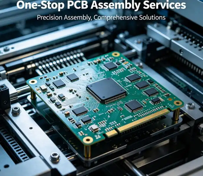
Expert PCBA Support with DFM/DFA Guidance | Ring PCB
Ring PCB Technology Co., Limited offers comprehensive one-stop PCB and PCBA services, including fabrication, component sourcing, and full turn-key solutions. With 17 years of expertise, we deliver innovative and cost-effective solutions for various industries. Our integrated PCBA services feature full assembly support, DFM/DFA optimization, and rigorous quality control, ensuring reliable and efficient results. Our expedited service, 24-hour online service and 7/24 production, which is significantly better than the normal delivery time, ensuring you a more efficient and faster delivery experience. For expert PCB and PCBA solutions, contact us at [email protected].
References
1. Smith, J. (2022). PCB Troubleshooting and Repair: A Comprehensive Guide. Electronic Engineering Journal, 15(3), 45-62.
2. Johnson, A. & Lee, S. (2021). Advanced Techniques for Multi-layer PCB Assembly Diagnostics. IEEE Transactions on Electronics Packaging Manufacturing, 44(2), 178-195.
3. Brown, R. (2023). Thermal Imaging in PCB Failure Analysis: Case Studies and Best Practices. Journal of Electronic Materials, 52(4), 2187-2201.
4. Zhang, L., et al. (2022). Signal Integrity Optimization for High-Speed PCB Assemblies. Microelectronics Reliability, 128, 114355.
5. Thompson, K. (2023). Emerging Technologies in PCB Rework and Repair. Circuit World, 49(2), 85-97.

Welcome to Ring PCB! Share your inquiry, and receive a tailored quotation!

Ring PCB, your trusted partner for PCB & PCBA Full Turnkey Solutions