Multilayer PCB vs HDI PCB: Signal Integrity in Advanced PCB Assembly
When looking at Multilayer PCB Assembly choices for your next project, it's important to know the main differences between multilayer and HDI (High-Density Interconnect) methods to make sure that the signals stay intact. In advanced electronic applications, each method has its own benefits. Multilayer designs offer strong stackup configurations that work well for automotive and industrial systems, while HDI technology makes it possible to make electronics smaller and faster for telecommunications and consumer electronics. Which of these technologies you choose has a big effect on communication quality, the difficulty of making the product, and its general dependability.

Introduction
Integrity of the signal has become an important part of current electronics design, especially as devices get smaller and rates keep going up. Choosing the right PCB technology is important for procurement managers and engineering teams that need to deal with today's competitive market. It has a direct effect on product performance, manufacturing prices, and time-to-market.
This in-depth study looks at layered and HDI PCB technologies with the goal of improving signal security. We look at how each method deals with common problems like electromagnetic interference, reducing crosstalk, and controlling impedance. We also think about real issues like how hard it is to put together, how much it costs, and what the provider can do.
For modern electronics to work with fast digital data, accurate analog circuits, and complicated mixed-signal tasks, PCB solutions are getting more complex. By knowing these requirements, you can make an informed choice between the multilayer and HDI approaches, making sure that your end product meets both performance requirements and market standards.
Understanding Multilayer and HDI PCBs: Definitions and Core Differences
Multilayer PCB Architecture and Applications
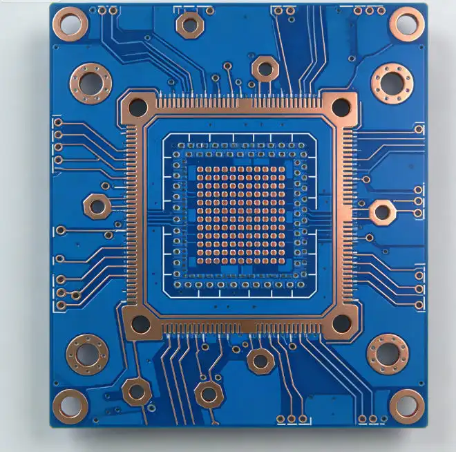
Multilayer PCBs have many electrical layers separated by dielectric materials. In advanced uses, there are usually between four and eighty layers. These boards work great in situations where strong electrical performance, a lot of current carrying ability, and stable operation in tough conditions are needed. Multilayer designs are often used in automotive electronics, aircraft systems, and industrial control tools because they are reliable and cost-effective when making a lot of them.
Dedicated power and ground planes are made possible by the layer stackup in multilayer boards. These provide great noise reduction and stable reference voltages for sensitive electronics. This arrangement works especially well for mixed-signal systems where analog and digital parts need to work together without interfering with each other. The methods used to make layered boards are well-known, so quantities and quality are always the same between production runs.
HDI Technology and Miniaturization Advantages
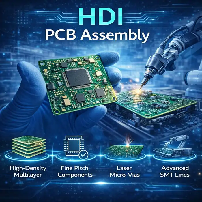
Multilayer PCB Assembly Microvias, hidden vias, and fine-pitch wiring are all used on HDI PCBs to increase the number of connections while reducing the size of the board. Usually, these boards have via-in-pad technology that lets you make direct connections under component packages. This makes much better use of room and improves electrical performance. HDI technology is being used more and more in telecommunications equipment, smartphone circuits, and high-performance computer applications to meet strict size and performance standards
When compared to regular through-hole vias, microvia structures in HDI boards, which are usually laser-drilled to diameters of 0.1mm or less, allow for quicker signal routes and less parasitic effects. This design lets you have more layers on a board while keeping the overall thickness small. This makes HDI perfect for portable devices and applications that need to save room.
Signal Integrity Fundamentals
Maintaining signal integrity means keeping the quality of the signal while electrical impulses move through PCB lines and interconnects. Impedance matching, minimizing noise, and electromagnetic compatibility are some of the most important factors. Multilayer and HDI technologies both deal with these problems in different ways, and each has its own benefits that depend on the needs of the application.
As signal frequencies go up, controlled impedance becomes more important, which calls for accurate trace shapes and stable dielectric qualities. Maintaining signal integrity across the circuit board is helped by ground plane continuity, via stub management, and return path optimization.
Signal Integrity in Multilayer vs HDI PCB Assembly: Technical Analysis
Multilayer PCB Signal Integrity Characteristics
Well-defined layer stackups that split signal layers with power and ground planes make multilayer designs very good at keeping signals intact. This set-up naturally separates the signal layers, lowering crosstalk and giving stable reference planes for controlling resistance. While multilayer boards' relatively big via structures can cause some unwanted side effects, they also provide low-resistance paths and strong mechanical links.
It is very important for stackup engineering to pay close attention to the dielectric width, material choice, and layer layout on a multilayer board. When signal traces run between two ground planes in a stripline arrangement, they provide excellent electromagnetic shielding and known impedance properties that are good for high-speed digital signals.
HDI PCB Signal Integrity Advantages and Challenges
Through shorter signal routes and less parasitic effects, HDI technology provides better signal integrity for high-frequency uses. Smaller via shapes reduce capacitive loading on signal traces, and since vias can be placed right under component pads, there is no need for breakout traces that can lower signal quality.
But HDI boards have special problems, like having to be made with smaller margins and being more sensitive to changes in the process. Because there are more interconnects, careful electromagnetic modeling is needed to keep neighboring circuits from connecting in ways that aren't wanted. In complex HDI designs, it's necessary to use advanced modeling tools to predict and improve signal behavior.
Comparative Performance Analysis
According to research, HDI boards can achieve 15-20% better signal integrity performance than layered designs that are the same. This is mostly because they have fewer parasitic effects and shorter connection lengths. But this benefit comes at a higher cost and makes production more difficult, with price increases of 30 to 50 percent based on the HDI features that are needed.
When it comes to electromagnetic interference, the two technologies are very different. Multilayer boards are better at protecting large areas, while HDI boards are better at isolating single signals. The choice is usually based on the needs of the program and the main sources of noise in the target area.
Advanced Assembly Processes and Challenges in Multilayer and HDI PCBs
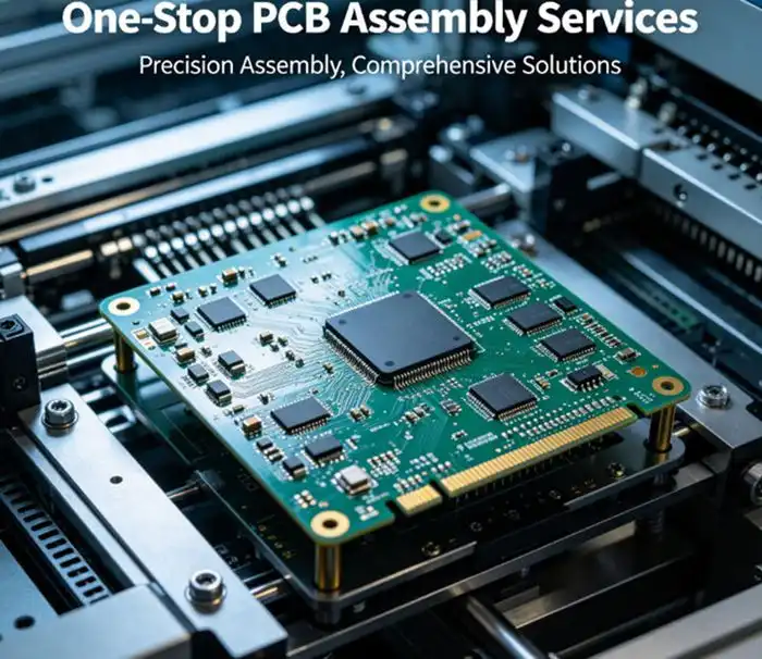
Multilayer PCB Assembly Considerations
Multilayer PCB Assembly standard layered assembly processes are helped by manufacturing methods that have been around for a while and quality control practices that are well known and used. The bigger via sizes and wider trace shapes give more process margins, which lowers the chance of assembly errors and raises the total yield rates. There are still not many limits on the types of packages and their positions, which means that placing components is still very flexible.
Automated optical inspection (AOI), in-circuit testing, and functional proof are all tried-and-true ways to check the quality of multilayer systems. By using these tried-and-true methods, all defects can be found while keeping test times and costs low. Because layered boards are strong, they can be reworked when needed. This helps with both prototype development and low-volume production.

HDI Assembly Complexity and Requirements
HDI assembly needs advanced production tools, such as high-precision drilling equipment, unique laminate methods, and better checking systems. For the microvia structures, precise laser drilling is needed with an accuracy of better than ±25 microns, and for the fine-pitch routing, advanced printing and etching methods are needed.
When putting components on HDI boards, you need to think carefully about where the vias are located and how to handle heat. During assembly, the high connection density can cause thermal hot spots, especially when lead-free welding is used. To make solder joints that are reliable without hurting the fine-pitch structures, you need to use advanced thermal profile and specific flux chemicals.
Quality Control and Testing Protocols
HDI and layered systems both have to meet strict quality standards, but there are big differences in how they are checked. HDI boards need to be inspected with a high-resolution X-ray to make sure the microvias are solid and to find any possible gaps in the solder joins. Because HDI circuits have fine pitches, flying probe testing is more difficult and sometimes needs special test tools or boundary scan methods.
Because HDI manufacturing has smaller process gaps and is more sensitive to defects, statistical process control is very important. Monitoring the accuracy of the cutting, the width of the plating, and the impedance characteristics all the time helps keep the quality uniform across production runs.
Evaluating Costs, Lead Times, and Partner Selection for PCB Assembly
Cost Analysis and Volume Considerations
The prices of putting together multilayer PCBs go down as more are made, which makes them a good choice for medium to large production runs. Standard materials and well-known ways of making things keep base prices low, and the ability to change the number of layers lets you find the best balance between function and cost. The costs of prototypes stay low because they are easy to make and don't need a lot of special tools.
The high costs of putting together HDI represent the complex manufacturing processes and specialized tools needed for microvia processing. Even though the setup costs are higher at first, the better power performance and reduced room can make the extra cost worth it in situations where these factors are very important. When production amounts go over a few thousand units per year, volume price gets a lot better.
Lead Time Expectations and Quick-Turn Capabilities
Depending on the number of layers and how complicated they are, standard multilayer boards usually take two to three weeks for prototypes and four to six weeks for production quantities. The well-established supply chain and methods allow for quick turnaround times for important projects. With accelerated processing, prototypes can often be delivered in 5 to 7 days.
Due to the unique steps needed to make them and the smaller number of suppliers, HDI boards usually have longer wait times. Deliveries of prototypes usually take three to four weeks, while deliveries of final numbers may take six to eight weeks. But HDI manufacturers with a lot of knowledge and special tools can speed up services for important projects.
Supplier Selection Criteria
To find the best manufacturing partner, you need to carefully look at their professional skills, quality systems, and service levels. Some important things to think about are the level of IPC certification, the skills of the tools, and the amount of experience with similar projects. For multilayer systems, look for quality measures that have been used consistently and a track record of success. HDI assembly partners should show that they have invested in advanced process controls and specialized tools.
When choosing a provider, geography is an important factor that needs to be balanced with cost benefits, the ease of contact, and logistics needs. The standards you need to get certified, like ISO9001, IATF16949, and standards specific to your business, should match up with what your quality system needs and what your customers expect.
Best Practices and Design Tips to Optimize Signal Integrity in Multilayer and HDI PCBs
Multilayer Design Optimization Strategies
For layered design to work, it's important to plan the stackup correctly, taking into account the needs of the signal layer, the power distribution needs, and the electromagnetic compatibility goals. Putting high-speed digital data on stripline layers between ground planes blocks noise very well and lets you control the resistance. The arrangement of the power plane should keep voltage drops to a minimum while giving all signal levels stable references.
The following design rules improve the security of signals on layered PCBs:
- Keep the ground planes under the high-speed signal layers constant.
- Use controlled impedance routing and make sure you know how to figure out the trace width.
- Use stitching to join together split ground planes.
- Use single-point links to separate the analog and digital ground areas.
- Decoupling capacitors should be placed near power pins in a smart way.
Together, these optimization methods build a strong electrical environment that lets signals get through reliably in a range of working situations. Multilayer PCB Assembly execution, when done right, lowers electromagnetic emissions and raises noise levels and system dependability.
HDI Design Excellence Guidelines
To make an HDI design work, you have to use the technology's special features while also dealing with its inherent complexity. Placing microvias should keep signal line lengths as short as possible while avoiding congestion that could lower factory yield. Layer planning is more important because there are more routes and you have to think about heat.
Important things to think about when designing an HDI include managing the microvia aspect ratio, making sure that the copper thickness in drilled holes is right, and planning for changes in how different materials expand and contract when heated. When using via-in-pad methods, you should be careful and think about how the parts will be put together and how reliable they need to be in the long run. When placing components, you need to think about how the high route density limits access.
Design for Manufacturing Integration
For signal integrity optimization to work, the design and manufacturing teams must work together closely throughout the entire development process. Electrical efficiency and production feasibility should both be looked at in design for manufacturability (DFM) reviews. This way, problems can be found before they affect costs or plans.
During the planning process, keeping in touch with your assembly partner on a regular basis can help you find ways to cut costs and increase yield without affecting the electrical performance. Early builds of prototypes give useful information about how to make things and let designers and builders improve both the concept and the way things are put together.
Conclusion
Choosing between multilayer and HDI PCB methods has a big effect on how well signals work, how much it costs to make, and how long a project takes. Because they are reliable and don't cost too much, multilayer designs are great for situations where room is limited but performance standards must be met. HDI technology offers better miniaturization and better electricity performance for advanced uses that are willing to pay for the more difficult production process that comes with it.
For either technology to be successfully used, Multilayer PCB Assembly design standards, manufacturing skills, and supplier partnerships need to be carefully thought through. The choice should strike a balance between the needs for scientific performance and the facts of business, such as development schedules, production volumes, and cost goals. Working with skilled manufacturers during the planning phase guarantees the best results for both electrical performance and production efficiency
FAQ
What are the main advantages of HDI PCBs over traditional multilayer designs?
HDI PCBs have many benefits, such as smaller boards, better signal integrity from shorter connection lines, and better electrical performance from smaller via parasitic effects. Because microvias can be placed right under component packages, breakout routing is not needed. This saves room and makes the electrical properties better. HDI technology also lets you have more layers on a board that is smaller overall.
How do you ensure quality in multilayer PCB assembly services?
Comprehensive inspection procedures, such as automatic optical inspection (AOI), in-circuit testing, and impedance verification, are used to make sure the quality of multilayer PCB assembly. IPC standards should be followed by certified assembly partners, and statistical process control should be used to keep an eye on important factors. Quality measures and source quality systems should be checked and audited on a regular basis to make sure that performance stays the same throughout production runs.
What are typical lead times and cost drivers for multilayer and HDI PCB orders?
Lead times for multilayer PCBs are usually between two and four weeks for prototypes and six to eight weeks for production volumes. Lead times for HDI boards are between three and four weeks for prototypes and six to eight weeks for production volumes. Layer count, board complexity, material choice, and number needs are some of the things that affect costs. Due to their unique processing needs, HDI boards cost 30–50% more than other boards. However, they offer space and speed benefits that can make the investment worthwhile in the right situations.
Partner with Ring PCB for Advanced Multilayer PCB Assembly Solutions
Ring PCB Technology offers top-notch multilayer PCB assembly services that are reliable, affordable, and have the fastest arrival times in the industry. Our 18 years of experience making things and full turnkey services make sure that your projects get the technical quality and quick service that your business needs. As a well-known company that makes multilayer PCB assemblies, we use cutting-edge 48-layer circuit board technology and keep all of our ISO certifications to make sure that the quality of our work is always high.
Our low prices and fast service allow us to offer online help 24 hours a day, seven days a week, and production plans that never end. This means that we can finish projects much more quickly than usual. Email our engineering team at [email protected] to talk about your unique needs and find out how our proven assembly skills can help you speed up the development of your product while still keeping the highest quality standards. For your next multilayer PCB assembly job, see how dedicated knowledge and advanced manufacturing skills can make a difference.
References
1. Johnson, H., & Graham, M. (2019). High-Speed Signal Propagation: Advanced Black Magic. Prentice Hall Professional Technical Reference.
2. IEEE Standards Association. (2018). IEEE 802.11ax Standard for Information Technology: Signal Integrity Requirements for High-Density PCB Applications.
3. Brooks, D., & Adam, S. (2020). PCB Design Guidelines for HDI Technology: Manufacturing and Electrical Performance Considerations. Institute of Electrical and Electronics Engineers.
4. International Electronics Manufacturing Initiative. (2021). Advanced PCB Assembly Processes: Quality Control and Testing Methodologies for Multilayer and HDI Technologies.
5. Zhang, L., Chen, W., & Roberts, K. (2022). Electromagnetic Compatibility in Modern PCB Design: Comparative Analysis of Multilayer and HDI Approaches. Journal of Electronic Manufacturing Technology.
6. Smith, R., & Davis, M. (2023). Cost-Effective PCB Assembly Strategies: Balancing Performance Requirements with Manufacturing Economics. Electronics Production and Test Magazine.

Welcome to Ring PCB! Share your inquiry, and receive a tailored quotation!

Ring PCB, your trusted partner for PCB & PCBA Full Turnkey Solutions