The Importance of PCB Inspection in Manufacturing
PCB inspection is a crucial step in the production of high-quality electronic devices. As technology advances, printed circuit boards become increasingly complex, with more layers, smaller components, and tighter tolerances. This complexity necessitates rigorous inspection processes to ensure the reliability and functionality of the final product.
Effective PCB inspection helps manufacturers identify and rectify issues early in the production process, reducing costly rework and minimizing the risk of field failures. By implementing a comprehensive inspection strategy, companies can maintain high quality standards, improve customer satisfaction, and enhance their reputation in the competitive electronics market.
Common Defects Detected During PCB Inspection
PCB inspection methods are designed to catch a wide range of potential defects that can occur during the manufacturing process. Some of the most common issues include:
- Solder bridging between adjacent components
- Missing or misaligned components
- Open or short circuits
- Insufficient solder joints
- Component polarity errors
- Damaged or cracked components
- PCB substrate defects such as delamination or warpage
By utilizing a combination of inspection techniques, manufacturers can detect these defects at various stages of production, ensuring that only high-quality boards progress to the next phase of assembly or shipment.
Automated Optical Inspection (AOI) in PCB Manufacturing
Automated Optical Inspection (AOI) is a non-contact inspection method that uses high-resolution cameras and advanced image processing algorithms to examine PCBs for visual defects. This technique is particularly effective for surface-mount technology (SMT) assembly and through-hole component placement verification.
How AOI Works in PCB Inspection?
During AOI, the PCB is illuminated with various lighting techniques, and high-resolution cameras capture images of the board from multiple angles. These images are then compared to a predefined "golden board" or CAD data to identify any discrepancies. Advanced software algorithms analyze the images, detecting issues such as:
- Component presence and placement accuracy
- Solder joint quality
- Component polarity
- Solder paste deposition
- Copper trace integrity
AOI systems can inspect thousands of solder joints per minute, making them an essential tool for high-volume PCB production. The technology's speed and accuracy contribute to improved throughput and reduced human error in the inspection process.
Benefits and Limitations of AOI in PCB Testing
AOI offers several advantages in PCB inspection:
- High-speed inspection capabilities
- Consistent and objective results
- Early detection of surface-level defects
- Reduced reliance on manual inspection
- Compatibility with Industry 4.0 and smart factory initiatives
However, AOI also has some limitations:
- Inability to detect internal defects or hidden solder joints
- Potential for false positives due to lighting or angle variations
- Limited effectiveness for inspecting complex, multi-layer boards
To overcome these limitations, manufacturers often combine AOI with other inspection methods for comprehensive quality assurance.
X-ray Inspection: Seeing Beyond the Surface
X-ray inspection is a powerful non-destructive testing method that allows manufacturers to examine the internal structures of PCBs, components, and solder joints. This technique is particularly valuable for inspecting multi-layer boards, ball grid arrays (BGAs), and other complex components that are challenging to assess visually.

Types of X-ray Inspection Systems
There are two main types of X-ray inspection systems used in PCB manufacturing:
- 2D X-ray Systems: These systems provide a top-down view of the PCB, offering a clear image of component placement and solder joint quality. 2D X-ray is effective for detecting issues such as solder bridges, voids, and misalignments.
- 3D X-ray Systems (Computed Tomography): These advanced systems create a three-dimensional representation of the PCB, allowing for detailed analysis of internal structures. 3D X-ray is particularly useful for inspecting complex, multi-layer boards and detecting hidden defects.
Applications of X-ray in PCB Inspection
X-ray inspection is invaluable for detecting defects that are not visible to the naked eye or AOI systems. Some key applications include:
- Inspecting BGA and QFN (Quad Flat No-lead) solder joints
- Detecting voids in solder connections
- Verifying internal layers in multi-layer PCBs
- Identifying cracks or defects in components
- Assessing the quality of through-hole solder joints
- Detecting counterfeit components
By incorporating X-ray inspection into their quality control processes, manufacturers can significantly enhance their ability to produce high-reliability PCBs for demanding applications such as automotive, aerospace, and medical devices.
In-Circuit Testing (ICT): Verifying Electrical Integrity
In-Circuit Testing (ICT) is an electrical test method that examines individual components and connections on a PCB to ensure proper functionality. This technique uses a "bed of nails" fixture to make contact with specific test points on the board, allowing for rapid and accurate testing of large production runs.
The ICT Process in PCB Inspection
The ICT process typically involves the following steps:
- Fixture Design: A custom test fixture is created with spring-loaded pins (the "bed of nails") that correspond to specific test points on the PCB.
- Board Placement: The PCB is placed on the fixture, and vacuum or mechanical pressure ensures proper contact between the test pins and the board.
- Electrical Testing: The ICT system applies test signals to various points on the board, measuring resistance, capacitance, and other electrical parameters.
- Data Analysis: The measured values are compared to predetermined thresholds to identify any deviations or faults.
- Reporting: The system generates a detailed report of the test results, highlighting any failed components or connections.
Advantages and Challenges of ICT
ICT offers several benefits in PCB inspection:
- High-speed testing capabilities for large production volumes
- Comprehensive electrical verification of components and connections
- Ability to detect both manufacturing defects and faulty components
- Precise measurements for analog and digital circuits
- Integration with automated handling systems for efficient production
However, ICT also faces some challenges:
- High initial cost for fixture design and fabrication
- Limited flexibility for testing different board designs
- Potential for damage to sensitive components due to probe contact
- Difficulty in accessing test points on densely populated or multi-layer boards
To address these challenges, many manufacturers combine ICT with other inspection methods or explore alternative techniques such as flying probe testing for smaller production runs or frequently changing designs.
Functional Circuit Testing (FCT): Ensuring Overall Performance
Functional Circuit Testing (FCT), also known as functional testing or end-of-line testing, is a comprehensive method that evaluates the overall performance of a PCB assembly. Unlike ICT, which focuses on individual components and connections, FCT simulates the actual operating conditions of the board to verify its functionality as a complete system.
The FCT Process in PCB Inspection
The FCT process typically involves the following steps:
- Test Plan Development: Engineers create a test plan that outlines the specific functions and parameters to be evaluated based on the product's specifications.
- Fixture Design: A custom fixture is developed to interface with the PCB's inputs, outputs, and power connections.
- Signal Generation: The FCT system generates input signals that simulate real-world operating conditions.
- Performance Measurement: The system measures the board's outputs and compares them to expected values.
- Environmental Testing: In some cases, FCT may include temperature cycling or other environmental stress tests to evaluate performance under various conditions.
- Data Analysis and Reporting: The system analyzes the test results and generates a comprehensive report on the board's functionality.
Benefits and Considerations of FCT
FCT offers several advantages in PCB inspection:
- Comprehensive evaluation of the PCB's overall functionality
- Ability to detect issues that may not be apparent through other inspection methods
- Verification of performance under simulated real-world conditions
- Identification of intermittent faults or timing-related issues
- Flexibility to adapt to different board designs and product specifications
However, there are also some considerations when implementing FCT:
- Longer test times compared to other inspection methods
- Higher complexity in test development and fixture design
- Potential for increased costs due to specialized equipment and software
- Need for ongoing maintenance and updates to test procedures as products evolve
Despite these challenges, FCT remains an essential step in ensuring the quality and reliability of complex electronic assemblies, particularly for high-value or safety-critical applications.
Conclusion
PCB inspection is a critical aspect of electronic manufacturing, ensuring the quality, reliability, and performance of printed circuit boards. By implementing a comprehensive inspection strategy that incorporates AOI, X-ray, ICT, and FCT, manufacturers can detect a wide range of defects and verify the functionality of their products.
Each inspection method offers unique advantages and plays a crucial role in the quality assurance process. AOI provides rapid visual inspection, X-ray allows for internal examination of complex assemblies, ICT verifies electrical integrity, and FCT ensures overall system performance.
As PCB complexity continues to increase, the importance of robust inspection processes becomes even more pronounced. Manufacturers and suppliers must stay abreast of the latest inspection technologies and methodologies to maintain high quality standards and meet the demanding requirements of industries such as automotive, aerospace, and medical devices.
FAQ
What is the difference between AOI and X-ray inspection?
AOI uses cameras to inspect the surface of PCBs, while X-ray inspection can examine internal structures and hidden solder joints.
How does ICT differ from FCT?
ICT tests individual components and connections, while FCT evaluates the overall functionality of the assembled PCB.
Are all four inspection methods necessary for every PCB?
The choice of inspection methods depends on the complexity of the PCB, production volume, and end-use requirements. Some applications may require all four, while others may use a combination of two or three methods.
Expert PCB Manufacturing and Assembly Services | Ring PCB
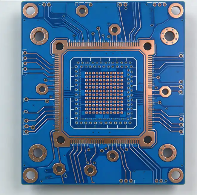
At Ring PCB, we offer comprehensive PCB manufacturing and assembly services, leveraging advanced inspection techniques to ensure superior quality. Our state-of-the-art facility employs AOI, X-ray, ICT, and FCT for thorough quality assurance. We specialize in complex, multi-layer HDI PCBs, providing one-stop PCBA services from prototyping to high-volume production. With our expertise in challenging processes and commitment to reliability, we deliver engineering-level solutions for diverse industries. Contact us at [email protected] for your PCB and PCBA needs.
References
1. Smith, J. (2022). Advanced PCB Inspection Techniques: A Comprehensive Guide. Journal of Electronics Manufacturing, 15(3), 78-92.
2. Johnson, A., & Lee, S. (2021). Comparative Analysis of AOI and X-ray Inspection in High-Density PCB Manufacturing. IEEE Transactions on Electronics Packaging Manufacturing, 44(2), 156-170.
3. Brown, R. (2023). In-Circuit Testing vs. Functional Testing: Optimizing PCB Quality Assurance. International Journal of Electronics Production, 29(4), 412-428.
4. Zhang, L., et al. (2022). Machine Learning Approaches in Automated Optical Inspection for PCB Defect Detection. Robotics and Computer-Integrated Manufacturing, 73, 102231.
5. Patel, N., & Garcia, M. (2023). The Role of X-ray Computed Tomography in Advanced PCB Inspection. Journal of Nondestructive Evaluation, 42(1), 1-15.