Essential High-Frequency Design Guidelines for 5G PCB Assembly
The rollout of 5G technology has revolutionized wireless communication, demanding advanced high-frequency design techniques for PCB assembly. Essential guidelines for 5G PCB assembly include utilizing low-loss materials, implementing proper stackup design, and employing advanced routing techniques. Engineers must also consider electromagnetic interference (EMI) shielding, thermal management, and signal integrity to ensure optimal performance. By adhering to these critical design principles, manufacturers can create robust and efficient 5G PCB assemblies that meet the stringent requirements of next-generation wireless networks.

Introducing High-Frequency PCB Design for 5G Applications
The Importance of Material Selection in 5G PCB Design
When it comes to 5G PCB assembly, material selection plays a pivotal role in determining the overall performance of the circuit board. High-frequency applications require materials with low dielectric loss and consistent electrical properties across a wide range of frequencies. Rogers Corporation and Taconic are among the leading manufacturers of high-frequency PCB materials, offering products specifically designed for 5G applications.
These advanced materials, such as Rogers RO4000 series or Taconic TLY-5, exhibit excellent electrical and mechanical stability, crucial for maintaining signal integrity in high-speed, high-frequency environments. The choice of material directly impacts the PCB's ability to handle the increased data rates and reduced latency demanded by 5G technology.
Stackup Design Considerations for 5G PCBs
The stackup design is another critical aspect of 5G PCB assembly. A well-designed stackup helps mitigate signal integrity issues and reduces electromagnetic interference. For high-frequency applications, it's essential to maintain consistent impedance throughout the board, which often requires the use of controlled impedance traces.
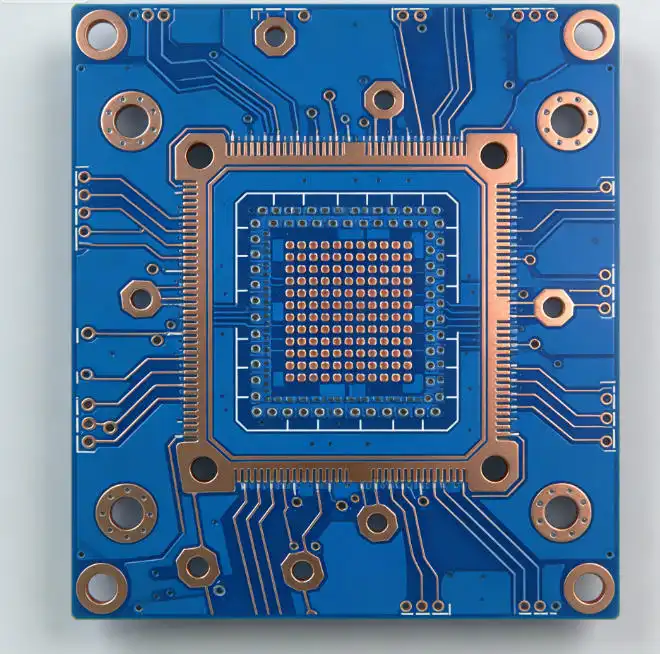
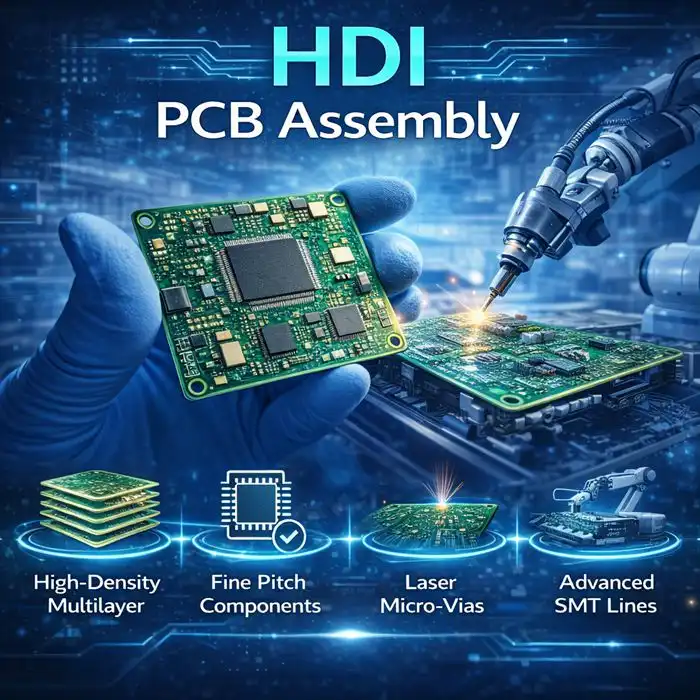
Designers typically employ multilayer stackups with strategically placed ground planes to minimize crosstalk and improve signal integrity. The use of buried vias and microvias is common in high-density interconnect (HDI) designs, allowing for more compact layouts and improved signal routing in complex 5G PCB assemblies.
Advanced Routing Techniques for High-Frequency Signals
Routing high-frequency signals in 5G PCB assembly requires specialized techniques to preserve signal integrity. Designers must consider factors such as trace width, spacing, and length to maintain consistent impedance and minimize signal reflections. The use of differential pair routing is prevalent in high-speed digital designs, helping to reduce electromagnetic interference and improve signal quality.
Advanced routing techniques also include the implementation of stripline and microstrip transmission lines, which are essential for controlling impedance in high-frequency circuits. Additionally, designers must carefully manage return paths and avoid discontinuities that can cause signal degradation in 5G PCB assemblies.
Addressing EMI and Thermal Challenges in 5G PCB Assembly
Effective EMI Shielding Strategies for 5G PCBs
Electromagnetic interference (EMI) is a significant concern in 5G PCB assembly due to the high frequencies and increased component density. Implementing effective EMI shielding strategies is crucial to ensure the reliable operation of 5G devices. Common shielding techniques include the use of ground planes, guard traces, and faraday cages.
Advanced EMI shielding solutions for 5G PCB assembly may incorporate specialized conductive coatings or embedded shielding layers within the PCB stackup. The strategic placement of components and careful routing of high-frequency signals can also help minimize EMI issues in 5G designs.
Thermal Management Solutions for High-Frequency PCBs
The increased power density and higher operating frequencies of 5G PCB assemblies present significant thermal management challenges. Effective heat dissipation is crucial to prevent performance degradation and ensure the longevity of 5G devices. Thermal management solutions for high-frequency PCBs often include the use of thermal vias, copper coins, and advanced heat-spreading materials.
Designers may also employ techniques such as component placement optimization and the integration of heat sinks or cooling fans to manage thermal issues in 5G PCB assemblies. The use of advanced thermal simulation tools during the design phase can help identify and address potential hotspots before production.
Balancing EMI Shielding and Thermal Management in 5G Designs
One of the challenges in 5G PCB assembly is striking a balance between effective EMI shielding and efficient thermal management. EMI shielding solutions, such as metal enclosures, can impede heat dissipation, while some thermal management techniques may compromise shielding effectiveness.
To address this challenge, designers must carefully consider the interplay between EMI shielding and thermal management strategies. This may involve the use of thermally conductive EMI shielding materials or the strategic placement of ventilation openings in shielding enclosures. Advanced simulation tools that integrate both electromagnetic and thermal analyses can be invaluable in optimizing 5G PCB designs for both EMI and thermal performance.
Ensuring Signal Integrity in High-Frequency 5G PCB Assemblies
Advanced Signal Integrity Analysis Techniques
Maintaining signal integrity is paramount in 5G PCB assembly, where even minor imperfections can lead to significant performance degradation. Advanced signal integrity analysis techniques, such as eye diagram analysis and S-parameter simulation, are essential tools for high-frequency PCB design.
These techniques allow designers to evaluate signal quality, identify potential issues such as reflections or crosstalk, and optimize the PCB layout for optimal performance. Time-domain reflectometry (TDR) and vector network analysis (VNA) are also valuable tools for characterizing high-frequency PCB assemblies and ensuring signal integrity in 5G applications.
Impedance Control and Matching in 5G PCB Design
Precise impedance control is crucial in 5G PCB assembly to minimize signal reflections and maintain signal integrity. This involves careful consideration of trace geometry, dielectric properties, and stackup design to achieve the desired impedance characteristics. Impedance matching networks may be required to ensure optimal signal transfer between different sections of the PCB or between the PCB and external components.
Advanced PCB manufacturing techniques, such as laser-direct imaging and adaptive etching processes, can help achieve tighter tolerances and more consistent impedance control in high-frequency 5G PCB assemblies. The use of embedded passives and high-precision surface mount components also contributes to improved impedance matching and overall signal integrity.
Mitigating Signal Degradation in High-Speed Interfaces
High-speed interfaces in 5G PCB assemblies are particularly susceptible to signal degradation due to factors such as insertion loss, return loss, and crosstalk. Mitigating these issues requires a combination of careful PCB layout, appropriate material selection, and the use of signal conditioning techniques.
Advanced equalization techniques, such as pre-emphasis and de-emphasis, can help compensate for channel losses and improve signal quality in high-speed 5G interfaces. The use of advanced PCB materials with low dielectric loss and careful attention to via design and transition regions can also help minimize signal degradation in 5G PCB assemblies.
Conclusion
The successful implementation of 5G PCB assembly requires a comprehensive understanding of high-frequency design principles and adherence to essential guidelines. By carefully considering material selection, stackup design, EMI shielding, thermal management, and signal integrity, engineers can create robust and efficient 5G PCB assemblies that meet the demanding requirements of next-generation wireless networks. As 5G technology continues to evolve, staying abreast of the latest advancements in PCB design and manufacturing techniques will be crucial for developing innovative and high-performance 5G devices.
High-frequency design expertise for stable 5G signals | Ring PCB
Ring PCB Technology Co., Limited offers unparalleled expertise in high-frequency PCB design for 5G applications. Our solutions are engineered for 1 GHz–100+ GHz performance, utilizing low-loss materials like PTFE and Rogers for superior signal integrity. We provide customizable designs to meet specific size, frequency, and environmental requirements. With 17 years of experience, we deliver innovative, reliable, and cost-effective PCB and PCBA solutions for various industries.
Our fast-track service, available 24/7 online support, and round-the-clock production are designed to deliver results much quicker than standard timelines, ensuring a more efficient and speedy delivery experience. For more information on cutting-edge 5G PCB assembly solutions, please contact us at [email protected].
References
1. Johnson, H. W., & Graham, M. (2003). High-speed digital design: a handbook of black magic. Prentice Hall PTR.
2. Bogatin, E. (2018). Signal and power integrity-simplified. Prentice Hall Press.
3. Hall, S. H., & Heck, H. L. (2009). Advanced signal integrity for high-speed digital designs. John Wiley & Sons.
4. Swaminathan, M., & Engin, A. E. (2008). Power integrity modeling and design for semiconductors and systems. Prentice Hall Press.
5. Coombs, C. F., & Holden, H. T. (2016). Printed circuits handbook. McGraw-Hill Education.

Welcome to Ring PCB! Share your inquiry, and receive a tailored quotation!

Ring PCB, your trusted partner for PCB & PCBA Full Turnkey Solutions